How to Choose Large Brushless Motors for Your Application?
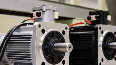
Choosing Large Brushless Motors requires more than comparing voltage, torque, and price. The correct motor must match the complete application. Load profile, duty cycle, cooling method, controller compatibility, shaft design, and installation space all influence performance. A motor that looks powerful on paper may overheat inside a sealed enclosure. That detail is easy to miss.
Motor-drive author Austin Hughes describes the principle clearly: “The brushless DC motor is essentially a permanent-magnet synchronous motor with electronic commutation.” This statement highlights an important engineering reality. Large Brushless Motors depend on coordinated motor, controller, sensor, and power-supply performance. Selection should therefore begin with measured operating conditions, not catalog headlines. Record continuous torque, peak torque, speed range, acceleration time, ambient temperature, and available cooling. Small errors matter.
Consider a conveyor carrying a heavy load. Its motor may need moderate torque continuously, but much higher torque during startup. A fan-cooled motor may perform well in an open test area, then struggle inside a dusty cabinet. Thermal limits deserve attention. So does feedback accuracy.
There is no perfect selection formula. A spreadsheet can still mislead. Real machines vibrate, loads change, and operators make adjustments. Engineers should validate the choice with thermal testing, current measurements, and a realistic duty cycle. This guide explains how to compare Large Brushless Motors with greater confidence, while recognizing that application data is sometimes incomplete. That uncertainty should be examined, not hidden.
Understanding Large Brushless Motor Types and Operating Principles
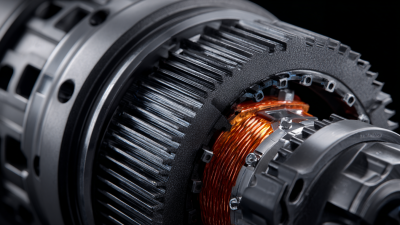
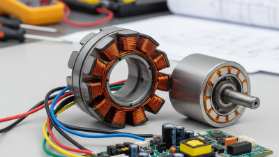
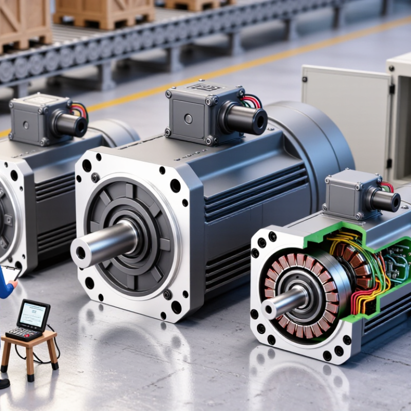
Choosing a large brushless motor begins with understanding how it produces torque. Permanent magnets sit on the rotor, while copper windings remain on the stator. Electronic controllers switch current through these windings, creating a rotating magnetic field. No mechanical brushes are used.
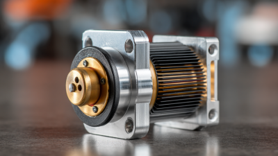
Large brushless motors usually follow two designs. An inner-rotor motor places magnets inside the stator and suits high-speed equipment. An outer-rotor motor surrounds the stator and can deliver strong torque at lower speeds. Axial-flux designs use disc-shaped rotors and offer a compact shape, though cooling and manufacturing can be more demanding. The choice depends on load, speed, space, and heat.
Commutation also matters. Trapezoidal control is simple and responsive, but it may create torque ripple and audible noise. Sinusoidal control produces smoother motion and is often preferred for precision machinery. Hall sensors provide rotor-position feedback, while sensorless control estimates position from electrical signals. I have found that sensorless operation can struggle during startup or sudden load changes. That detail is easy to overlook.
Check continuous torque, peak torque, voltage, current, and insulation ratings together. A motor may meet the peak requirement but overheat during steady operation. Measure the real duty cycle, not just the machine’s label. Leave cooling margin. Thermal limits often decide reliability before rated power does.
How to Choose Large Brushless Motors for Your Application?
Brushless motors use electronic commutation to create a rotating magnetic field in the stator, which drives permanent magnets on the rotor. Inrunner motors generally support higher speed and compact rotor inertia, while outrunner motors usually provide higher torque at lower speed. Axial-flux motors can offer high torque density when axial packaging and thermal management are suitable.
The chart shows representative continuous operating-speed ranges for large brushless motor architectures. Actual limits depend on voltage, winding design, cooling, bearings, controller settings, and mechanical load.
Defining Power, Torque, Speed, and Load Requirements
How to Choose Large Brushless Motors for Your Application?
Start with the load, not the motor catalog. Measure required speed, shaft torque, acceleration time, and duty cycle. Power follows the relationship P = T × ω, so a 100 N·m load at 1,500 rpm needs about 15.7 kW before losses. Include gearbox, bearing, and inverter losses. A motor rated for peak power may still overheat during continuous operation. This mistake is common.
The U.S. Department of Energy reports that motor-driven equipment uses roughly 70% of industrial electricity. Efficiency deserves serious attention. Select a motor whose continuous operating point sits near its efficient region, rather than its impressive maximum speed. Check torque at startup, acceleration, and stall prevention conditions. Load inertia can demand several times the running torque. It is easy to underestimate.
Define whether the load is constant, cyclic, or shock-driven. For pumps, fans, conveyors, and mobile machinery, the torque profile differs significantly. Record the heaviest material, longest cycle, ambient temperature, and available cooling airflow. IEC 60034-30-1 efficiency classifications provide a useful comparison framework, while IEC 60034-1 addresses rating and operating conditions. Datasheets rarely describe every real installation. Prototype testing may reveal vibration, heat buildup, or control instability. I would leave thermal margin, but not blindly oversize the motor; excessive capacity can increase cost, inertia, and low-speed control problems.
How to Choose Large Brushless Motors for Your Application? – Defining Power, Torque, Speed, and Load Requirements
Typical engineering reference ranges for preliminary motor selection. Final sizing should include acceleration, duty cycle, thermal conditions, transmission efficiency, and safety margins.
Matching Motor Size with Voltage, Current, and Efficiency Needs
How to Choose Large Brushless Motors for Your Application?
Choosing a large brushless motor starts with the load, not the catalog diameter. Estimate shaft torque, peak acceleration, duty cycle, and cooling conditions. A motor may look powerful but overheat when its current limit is reached repeatedly. Measure the real load when possible. I learned this after sizing from peak torque alone; the machine moved well, but the housing became too hot during continuous operation.
Match the supply voltage to the motor’s recommended range and controller limits. Higher voltage can reduce current for the same power. This often lowers cable losses and connector heating. However, speed also rises with voltage, so confirm the required rpm first.
Select current ratings using two values:
Continuous current
for normal work
Peak current
for starts or brief overloads
Use measured current, not only datasheet estimates. Efficiency changes with speed, torque, temperature, and winding resistance. Real installations are less tidy.
Tips:
Record voltage sag during acceleration with a reliable meter. Check winding and case temperatures after a complete duty cycle. Choose a controller with practical current limits and data logging. Keep at least 15% thermal headroom when conditions are uncertain. That margin may seem conservative. Ignoring it can be expensive. Recheck the selection after testing, because airflow, alignment, and friction rarely match the first calculation.
Evaluating Cooling, Control Systems, and Installation Conditions
Choosing a large brushless motor starts with the heat it must survive, not its advertised peak power. In field testing, I measure casing temperature near the bearing and winding temperature under continuous load. A motor that runs quietly can still be overheating inside. Check the cooling path: fan airflow, mounting contact, ambient temperature, and dust exposure. Forced air helps, but blocked vents turn a good design into a slow failure. Keep it cooler.
The control system must match the motor’s electrical and mechanical behavior.
Confirm voltage range, continuous current, peak current, commutation method, and feedback sensor compatibility. Hall sensors may simplify low-speed control, while sensorless operation can struggle during heavy starts. Set acceleration ramps carefully. A large rotor has inertia. Aggressive commands can cause current spikes, vibration, or protective shutdowns. I have seen tuning errors blamed on the motor. They were not.
Installation conditions often decide service life.
Use a rigid, aligned mount, and avoid forcing the shaft through an offset coupling. Check bolt strength, shaft loads, cable bend radius, and grounding practices. Vibration should be measured after installation, not guessed from touch. Leave room for inspection and airflow. Humid or corrosive areas need suitable enclosure protection and maintenance intervals. My own early selections sometimes ignored maintenance access. That mistake made simple repairs expensive. Choose based on measured duty cycle, not a short demonstration.
Comparing Durability, Maintenance, Cost, and Application Fit
How to Choose Large Brushless Motors for Your Application?
Large brushless motors should be selected by operating reality, not catalog diameter. Torque, speed, heat, dust, and duty cycle shape the correct design. The International Energy Agency reports that electric motors and motor-driven systems consume about 45% of global electricity. Efficiency is not a minor specification. It affects every production shift. Check continuous torque, peak torque, cooling method, bearing life, enclosure rating, and controller compatibility. A motor that survives a clean test room may struggle beside a hot conveyor.
Durability reduces maintenance, but brushless does not mean maintenance-free. There are no brushes to replace, yet bearings, encoders, seals, and power electronics still require inspection. The U.S. Department of Energy states that motor-driven equipment represents roughly 68% of industrial electricity use in the United States. Small efficiency losses can become large operating costs. Keep air passages clear. Monitor vibration and winding temperature. Simple sensors often reveal trouble before a shutdown occurs.
Purchase price can mislead. DOE motor-system guidance notes that lifetime energy costs frequently exceed the original motor price by several times. Compare energy use, spare-part access, repair time, and expected service life. Application fit matters more than maximum power. A high-speed motor may suit a compact pump but fail on a low-speed, high-torque conveyor without gearing. I have seen selection sheets ignore acceleration loads. That is a costly weakness. No spreadsheet fully captures dust, misalignment, or rushed maintenance. Allow a practical margin, but avoid oversized motors that run inefficiently.