Electric motors quietly drive pumps, fans, tools, and vehicle systems. The International Energy Agency and UNIDO estimated that electric motor-driven systems use about 45% of global electricity in their 2011 report, Energy-Efficiency Policy Opportunities for Electric Motor-Driven Systems. That scale makes motor design more than a technical detail. It affects energy use, operating costs, and the performance people notice every day.
A Bldc Electric Motor replaces mechanical brushes with electronic commutation. Permanent magnets sit on the rotor, while windings occupy the stator. A controller switches current through those windings in sequence, creating a rotating magnetic field that turns the rotor. Rotor position may be detected with sensors, or estimated from electrical signals such as back electromotive force. The result can be precise speed control and reduced brush-related wear. No brushes. But the motor does not work alone: the controller, power supply, cooling, and load all shape real-world efficiency. That distinction is easy to overlook.
This guide explains the main components, the commutation process, and how sensor-based and sensorless designs differ. It also considers practical trade-offs, including heat, control complexity, and upfront cost. A BLDC motor can be efficient, but “brushless” does not guarantee the best choice for every application. Useful engineering starts with the load.
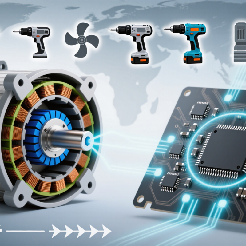
What defines a brushless DC motor is how it switches current, not simply the voltage it receives. Unlike a brushed motor, it has no carbon brushes rubbing against a rotating commutator. Instead, permanent magnets sit on the rotor, while copper windings are fixed around the stator. When the windings are energized in sequence, their magnetic field pulls the rotor around. No brushes. Less rubbing.
An electronic controller performs the switching, often using Hall sensors to detect the rotor’s position. Some designs estimate position from changes in voltage, avoiding those sensors. For example, as a small fan starts, the controller energizes selected windings, then changes the sequence as the rotor turns. The timing matters: poor timing can mean extra heat, noise, or reduced torque. The motor needs a controller; connecting it directly to a DC supply usually will not produce controlled rotation.
The name can mislead. A BLDC motor is supplied from a DC source, but its stator currents are switched electronically and may behave like multiphase alternating currents. That distinction is useful when comparing motor specifications. Not every design handles startup, speed control, or heat in the same way, so the label alone does not tell the whole story. In real use, load and cooling matter too. A compact motor in a warm enclosure may perform quite differently from the same motor with open airflow.
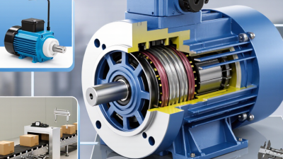
A BLDC motor turns electrical energy into rotation through three working parts: a stator, a permanent-magnet rotor, and an electronic controller. The stator’s copper windings sit in fixed slots around the motor. The rotor carries magnets and spins inside them. No brushes rub against a commutator. Instead, the controller switches current between winding phases to create a rotating magnetic field.
That switching needs timing. Hall sensors can report the rotor’s position to the controller; sensorless designs infer it from electrical signals. The controller then adjusts the sequence and current, affecting speed and torque. Bearings support the shaft, while the housing protects the assembly and helps release heat. Small parts matter. A loose bearing or poor heat path can undermine otherwise careful control.
The International Energy Agency has estimated that motor systems consume more than 40% of global electricity, a figure covering many motor types, not BLDCs alone. The U.S. Department of Energy’s motor-systems sourcebook reports that motor-driven systems use about 70% of U.S. manufacturing electricity. These figures explain why component selection matters: winding resistance, controller losses, and cooling all influence system efficiency. A sensorless setup may reduce hardware, but startup behavior can be less predictable under heavy loads. Real performance depends on the motor, controller, and application working together.
A BLDC motor turns electrical switching into rotation without brushes rubbing against a commutator. Permanent magnets sit on the rotor; copper windings surround it in the stator. An electronic controller energizes the windings in sequence, creating a magnetic field that pulls the rotor forward. Think of the coils taking turns tugging at a magnet. That is the basic motion.
The controller must track rotor position. Hall sensors can report it directly; sensorless designs estimate it from back-EMF, the voltage induced in inactive windings. The inverter then switches current between phases, often using pulse-width modulation to adjust torque and speed. Timing matters: at low speeds, back-EMF is weak, so sensorless control can be less certain. A tidy diagram can hide that practical wrinkle.
The U.S. Department of Energy’s 2014 motor-systems assessment estimated that motor-driven systems used 68% of U.S. manufacturing electricity. That figure covers many motor types, not BLDC motors alone, but it shows why efficient control matters. The IEA’s Global EV Outlook 2024 projected nearly 17 million electric-car sales that year, expanding demand for compact, controllable drives. Reports describe broad trends; the exact commutation method still depends on the motor and controller.
A BLDC motor has permanent magnets on its rotor and coils in its stator. Its controller switches current among the coils to keep the rotor turning. This electronic switching replaces the brushes used in brushed motors. The controller reads rotor position from Hall sensors or estimates it from electrical signals. Timing matters: switch too early or late, and the motor may run noisily or lose efficiency.
Speed and torque need different kinds of control. To change speed, the controller adjusts the voltage delivered to the motor, often by rapidly switching power on and off. A speed sensor or position estimate helps it compare actual speed with the requested speed. For torque, it regulates current, since motor torque generally rises with current within the motor’s operating limits. More load? More current may be needed. A current limit protects the windings and power electronics from excessive heat. In a practical setup, a fan slowing under load can prompt the controller to increase current and maintain rotation. But response depends on settings, sensor quality, and cooling; a controller cannot overcome every mechanical limit. It is easy to treat a speed setting as a guarantee. It is not.
| Topic | What Happens | Controller Input or Method | Effect on Speed and Torque |
|---|---|---|---|
| Motor construction | A brushless DC (BLDC) motor typically has permanent magnets on the rotor and windings on the stator. Electronic switching replaces the mechanical commutator and brushes used in a brushed motor. | The controller switches current through the stator windings in a timed sequence. | The rotating magnetic field produces continuous rotor motion. Removing brushes avoids brush wear and reduces brush-related electrical losses. |
| Electronic commutation | Commutation changes which motor phases carry current as the rotor turns. A common BLDC drive uses six-step, or trapezoidal, commutation. | Switching timing is based on rotor-position information from Hall sensors or, in sensorless drives, estimates derived from motor electrical signals. | Correct timing sustains rotation and helps produce torque. Poor timing can increase current, noise, and heating while reducing performance. |
| Three-phase inverter | Power transistors in a three-phase inverter connect the motor windings to the DC supply in controlled patterns. | The controller operates the transistors using a commutation sequence and pulse-width modulation (PWM). | PWM varies the effective voltage applied to the windings, allowing the controller to adjust motor operation without changing the supply itself. |
| Speed regulation | Motor speed is measured or estimated and compared with a requested speed. | A closed-loop controller, often using a proportional-integral (PI) algorithm, adjusts the drive command based on the speed error. | If the load slows the motor, the controller can increase its drive command within current, voltage, and thermal limits to restore speed. |
| Torque regulation | Motor torque is closely related to the current that produces the motor’s magnetic field, with the exact relationship depending on the motor and control method. | The controller measures or estimates phase current and adjusts PWM to track a current or torque request. | More controlled torque-producing current generally provides more torque, but also increases electrical losses and heat. |
| Field-oriented control (FOC) | FOC mathematically transforms measured phase currents into components associated with magnetic flux and torque, then controls them separately. | Rotor position is measured or estimated, and fast current-control loops adjust the inverter output. | FOC can provide smooth torque and precise control across a wide operating range. It requires more computation and accurate position and current information than basic six-step control. |
| Load changes | A higher mechanical load tends to reduce speed unless the motor produces additional torque. | The controller detects a speed error or a change in current demand and updates its output. | In speed-control mode, the controller can raise current to maintain the speed target, subject to available power and protection limits. |
| High-speed operation | As speed rises, the motor’s generated back electromotive force (back EMF) increases and leaves less voltage available to drive current. | Some drives use field weakening, where supported by the motor and control strategy, to extend operation above the base-speed region. | Field weakening can increase achievable speed, but may reduce available torque and increase current or heating. |
| Protection and limits | Current, voltage, and temperature can exceed safe operating values during overloads, faults, or demanding operation. | The controller monitors available sensor readings and applies limits, such as reducing output or shutting down the drive. | Protection helps prevent damage, but can temporarily restrict speed or torque when a limit is reached. |
| Regenerative braking | When the rotor is driven by the load, the motor can act as a generator and return electrical energy through a compatible drive. | The controller manages braking current and the flow of energy back to a supply or energy-storage system that can accept it. | Regeneration can provide braking torque and recover some energy; the amount depends on the drive, load, and receiving system. |
BLDC motors are commonly classified by rotor position and feedback method. Inrunner designs place the rotor inside the stator. They often suit high-speed tools, pumps, and compact appliances. Outrunner designs rotate an outer rotor around the stator. Their greater torque at lower speeds can suit direct-drive fans, camera gimbals, and many small aircraft. Compact, but not silent. Vibration and cooling still depend on the full assembly, not just the motor type.
A second distinction is sensored versus sensorless control. Sensored motors use position sensors, often Hall-effect sensors, to help the controller manage startup and low-speed movement. They can work well in e-bikes and industrial drives that need controlled starts. Sensorless systems estimate rotor position from electrical signals, reducing wiring and sensor parts. They are common in fans and other loads that reach steady speed quickly, but low-speed startup can be less reliable. That trade-off is easy to underestimate.
Slotless BLDC motors are another option. Their stators omit iron teeth, which can reduce cogging and produce smoother motion in small pumps, medical devices, and precision equipment. The design may cost more or require different thermal planning. Application labels are only a starting point; load, speed range, noise, and heat should be checked together. Real installations sometimes reveal a mismatch that a product sheet does not make obvious.
A brushless DC (BLDC) motor uses an electronic controller to switch current through its stator windings in sequence. This idealized waveform shows six-step commutation across one electrical cycle: +1 and −1 indicate opposite commanded current directions, while 0 indicates the phase is unenergized. Actual phase currents vary with motor design, load, and controller.
Common BLDC types include outrunner and inrunner motors, as well as sensored and sensorless designs. They are used in applications such as fans, pumps, power tools, electric bicycles, drones, and robotics.