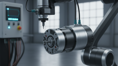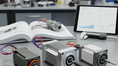
Brushless Servo technology is central to many machines that must move accurately, repeatedly, and smoothly. You can see its work in a robot arm placing a component, or a packaging line stopping at an exact position. The International Federation of Robotics’ World Robotics 2024 report counted 4,281,585 industrial robots operating worldwide in 2023. It also reported 541,302 new installations that year. These figures describe robot adoption, not servo-motor sales, but they show why controlled motion matters.
A brushless servo motor uses permanent magnets in its rotor and electrical windings in its stator. An electronic drive switches current through those windings, creating a rotating magnetic field that turns the rotor. A sensor, often an encoder or resolver, reports the motor’s position and speed. The drive compares that feedback with the requested motion and adjusts current to correct the difference. That matters. The result can be precise position, speed, or torque control, depending on the system and its setup. With no brushes to wear against a commutator, the motor avoids one common source of maintenance. It still needs proper thermal management, sound wiring, and attention to bearings. And a servo is not precise by itself. Tuning, load, and mechanical backlash can all affect performance. This guide explains what a Brushless Servo is, how its feedback loop works, and what to consider when choosing one.
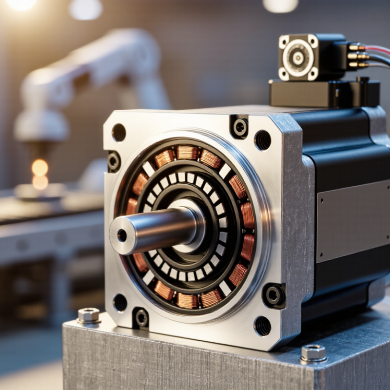
A brushless servo motor combines a brushless motor with a feedback system and a controller designed for precise motion. Its rotor typically contains permanent magnets, while coils sit in the stator. Electronic switching energizes those coils in sequence, turning the rotor without physical brushes rubbing against a commutator. No brushes are present. That usually means less brush-related wear, though bearings and insulation still need attention.
The servo part is defined by controlled position, speed, or torque—not by the motor alone. An encoder or resolver commonly reports the shaft’s movement to a drive, which adjusts current when the actual motion differs from the command. In a machine, this can mean moving a tool carriage a measured distance, then holding it steady under changing load. The feedback device, wiring, tuning, and mechanical setup all affect accuracy. A brushless motor without suitable feedback and control may not behave like a servo. In practice, the boundary can be less tidy: some systems use different feedback methods, and poor tuning can cause vibration even with a capable motor.
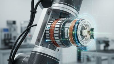
What Is a Brushless Servo Motor and How Does It Work?
Key Components and Their Roles
A brushless servo motor turns electrical commands into controlled movement without brushes rubbing against a commutator. Its controller switches current through the stator windings, creating a rotating magnetic field. Permanent magnets on the rotor follow that field. The result is precise motion, with less brush wear and maintenance. That matters.
The stator provides the magnetic push, while the rotor carries the magnets and output shaft. An encoder or resolver measures the shaft’s position and speed. The drive reads this feedback and adjusts current when the motor falls behind its command. Bearings support the shaft and help it turn smoothly. A servo is a system, not just a motor. Wiring, tuning, and mechanical load all affect performance.
Tips: Check that the encoder feedback matches the controller’s settings before testing motion. Secure the motor firmly, and inspect couplings for looseness. Listen for unusual vibration at low speed; it can reveal alignment problems. Not every rough movement comes from the motor itself. A poor tuning choice can cause it too, and diagnosing that takes patience.
Illustrative three-phase stator currents: The waveforms show idealized, normalized phase currents spaced 120 electrical degrees apart. A servo drive controls the stator currents to create a rotating magnetic field, which the rotor’s permanent magnets follow.
Key components: Stator windings generate the magnetic field; the permanent-magnet rotor produces motion; the encoder measures rotor position and speed; the servo drive switches and regulates current using that feedback; and the bearings support smooth rotor rotation.
A brushless servo motor has no brushes rubbing against a commutator. Instead, an inverter switches current through the stator windings in a timed sequence. Those energized coils create a magnetic field that pulls the rotor’s permanent magnets around. No contact switching. Just controlled current.
The controller needs to know where the rotor is. An encoder or resolver reports its position, and the inverter uses that feedback to energize the right winding phases. In many servo systems, current is adjusted continuously to control torque and speed. A small timing error can cause vibration, heat, or uneven motion. That matters when a motor must stop precisely beside a metal fixture or move a load smoothly.
The U.S. Department of Energy’s 2014 Industrial Motor Systems Market Opportunities Assessment estimated that motor-driven systems account for about 68% of U.S. manufacturing electricity use. That figure covers many motor types, not brushless servos alone, but it shows why efficient control matters. Electronic commutation can reduce mechanical wear, yet setup still counts. A poorly tuned feedback loop can make an advanced motor feel rough. Real machines are rarely perfect.
A brushless servo motor uses electronic switching to turn its rotor, while feedback tells the controller what the shaft is actually doing. An encoder mounted on the motor can report position many times per revolution. Some systems use a resolver instead, especially where rugged sensing is needed. The controller compares this measured position with the commanded position and calculates the difference. Small corrections matter.
When the shaft lags behind its target, the controller adjusts current in the motor windings to increase or redirect torque. As the shaft approaches the target, it reduces the correction to limit overshoot. This continuous process is called closed-loop control. For speed control, the controller tracks how quickly position changes over time, then adjusts motor output to hold the requested speed under changing load.
The feedback signal is useful, but it is not perfect. Encoder resolution, electrical noise, loose couplings, and mechanical backlash can all affect what the controller sees. A shaft may appear steady while the load at its far end still vibrates slightly. During setup, technicians often compare commanded motion with measured motion and adjust control settings. It can take more than one pass. If a system feels hesitant or oscillates near a stop, tuning or mounting details may need a closer look.
| System element or measure | What it does or represents | Example or reference value |
|---|---|---|
| Brushless motor construction | Permanent magnets are on the rotor; electrically switched windings are on the stator. An electronic drive commutates the windings, so brushes are not used for commutation. | The drive changes phase currents in step with rotor position to produce torque. |
| Position feedback device | An encoder, resolver, or Hall-effect sensors report rotor position or position-related signals to the drive. | An encoder provides position counts; Hall sensors typically provide coarser rotor-position information. |
| Encoder resolution example | Resolution describes the number of distinguishable feedback counts per revolution; it is not, by itself, a guarantee of absolute positioning accuracy. | A 17-bit single-turn value represents 217 = 131,072 counts per revolution, or about 0.00275° per count. |
| Position control loop | The controller compares commanded position with measured position and uses the resulting error to request motion. | If the commanded position is 90° and feedback reads 86°, the position error is 4°. |
| Speed feedback and control | The drive estimates or measures rotational speed from position feedback and adjusts motor torque to reduce the difference from the speed command. | 3,000 rpm equals 50 revolutions per second. |
| Current and torque control | The drive regulates phase current. In a permanent-magnet motor, torque is approximately proportional to torque-producing current within the motor's operating limits. | A higher torque command generally requires higher torque-producing current, subject to drive and motor limits. |
| Nested feedback loops | Many servo drives use cascaded current, speed, and position loops. The inner current loop responds to torque demand; the outer loops manage speed and position. | Typical command path: position target → speed demand → current/torque demand. |
| Closed-loop correction | Feedback lets the drive detect tracking error caused by changing load or disturbances and adjust its output while operating. | Actual performance depends on the motor, encoder, drive tuning, mechanics, load, and operating conditions. |
Note: Values shown are explanatory examples. Specifications and achievable accuracy vary by motor, feedback device, drive, and application.
A brushless servo motor uses electronic switching instead of brushes to create rotation. A feedback device reports shaft position and speed to the controller, which adjusts current as the load changes. This enables precise movement, even when a machine must stop at an exact point. There are no brushes to wear out, but the motor still needs careful setup.
These motors are common in robotic arms, packaging equipment, CNC machines, and automated inspection systems. They offer fast response, smooth speed control, and strong torque for their size. Performance depends on the motor, controller, feedback device, and load working together. Heat still matters. Repeated acceleration can raise winding temperatures, while a poorly matched motor may vibrate or struggle to hold position. A setup can look right on paper and still behave unpredictably in a real machine.
Tips: Match the motor’s continuous torque rating to the actual load, not just its brief peak demand. Check the required speed, stopping accuracy, and available cooling. Secure cables and tune the controller gradually; changing several settings at once makes faults harder to trace. Test under realistic operating conditions.