A motor rarely works alone. It responds to a load, a power source, and the control strategy around it. A Bldc Drive electronically commutates a brushless DC motor, helping regulate speed and torque without mechanical brushes. That design can reduce routine brush wear and support precise control. But the drive is not a shortcut to better performance. The motor, controller, and application must be matched.
In a ventilation unit, stable speed can help maintain airflow as demand changes. On a conveyor, controlled acceleration may reduce jolts as products move between stations. Small details matter: supply voltage, peak load, operating temperature, feedback method, and required speed range. A poorly matched drive can add cost, noise, or unwanted heat. Not ideal. Efficiency also depends on the full system, including the motor design and how it is operated.
This guide examines why engineers choose a Bldc Drive, where it can provide practical advantages, and what trade-offs deserve attention. It considers control accuracy, maintenance, energy use, integration, and application needs. No single drive fits every machine. Careful selection starts with measured operating conditions, not a headline specification. And sometimes, the first estimate is wrong. Reviewing real load data and testing the setup can reveal issues that a catalogue cannot. The goal is a reliable choice, supported by clear requirements and verified performance.
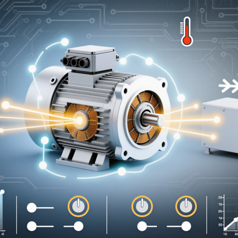
A BLDC drive is the electronic unit that controls a brushless DC motor. The motor has permanent magnets on its rotor and coils on its stator. Unlike a brushed motor, it has no brushes to switch current mechanically. Instead, the drive rapidly switches current through the motor’s phases, creating a rotating magnetic field that turns the rotor. That timing matters.
The drive uses rotor-position information to decide when each phase should be energized. Some systems read Hall sensors or an encoder; others estimate position from electrical signals. The drive can regulate speed and torque, manage acceleration, and protect against conditions such as excessive current. In a workshop, that can mean adjusting a conveyor’s speed or helping a small pump start smoothly. Details vary by motor and drive.
Choosing one is not just a matter of matching voltage. Current limits, load inertia, cooling, and control settings all affect performance. A drive that looks correctly sized on paper may still need careful tuning to avoid rough starts or speed fluctuations. Sensorless control can simplify wiring, but may perform differently at very low speeds. Small details count.
| Design or Control Aspect | What a BLDC Drive Provides | Why It Matters in an Application |
|---|---|---|
| Basic definition | A BLDC drive is an electronic controller that switches current through a brushless DC motor’s stator windings to produce rotation. | The drive and motor work as a system; motor selection, controller capability, and application requirements should be considered together. |
| Electronic commutation | Power switches energize the motor phases in sequence according to rotor position, replacing the mechanical commutator and brushes used in brushed motors. | Electronic switching avoids brush wear and supports controlled motor operation, but requires compatible control electronics. |
| Rotor-position feedback | Rotor position can be detected with sensors, such as Hall-effect sensors, or estimated by the controller using electrical signals such as back EMF. | Sensored control can provide rotor-position information at standstill. Sensorless methods can reduce sensor wiring but may require a suitable startup strategy and operating conditions. |
| Speed control | The drive can regulate motor speed by controlling the voltage and current applied to the windings, commonly using pulse-width modulation (PWM). | Adjustable speed can support processes that need variable airflow, fluid flow, or machine speed. The available range depends on the motor, drive, load, and control method. |
| Efficiency | Brushless construction eliminates brush-related electrical and friction losses. Overall system efficiency still depends on motor design, drive electronics, operating point, and load. | BLDC systems can be a good choice where energy use matters, but performance should be evaluated across the application’s actual duty cycle. |
| Maintenance | There are no brushes to replace, although bearings, wiring, connectors, cooling components, and the drive electronics may still require inspection. | Reduced brush maintenance can be useful in equipment intended for long operating periods or where routine access is difficult. |
| Torque and response | The drive controls phase current, which is closely related to motor torque within the motor’s operating limits. Acceleration and torque response depend on the control design and system sizing. | Appropriate current limits and motor sizing help meet starting, acceleration, and load-change requirements while protecting the motor and drive. |
| Thermal and protection features | Depending on its design, a drive may include current limiting, over-temperature protection, undervoltage or overvoltage handling, and fault reporting. | Check the drive’s documented protection functions and ratings; protection features vary and do not replace correct wiring, cooling, or system design. |
| Typical application fit | BLDC drives are used in applications such as fans, pumps, appliances, power tools, and automation equipment. | They are worth considering when an application benefits from electronically controlled speed, brushless operation, or a compact motor-drive system. |
| Selection checks | Match the drive to the motor’s voltage, current, phase configuration, feedback method, speed range, and required control interface. | Confirm continuous and peak operating requirements, load profile, cooling, environmental conditions, and any applicable safety or compliance needs before selection. |