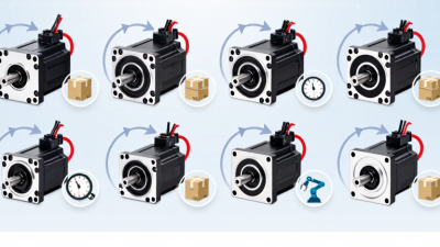
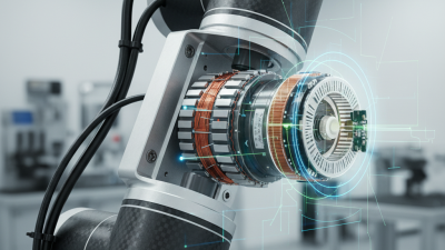
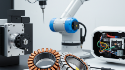
How to Choose a Brushless DC Servo Motor?
Choosing a Brushless Dc Servo Motor is not simply a matter of matching a power rating. The motor must meet the machine’s speed, torque, accuracy, and duty-cycle requirements. A unit that looks suitable on a catalog page may overheat, respond too slowly, or struggle with repeated starts.
Start with the actual load. Estimate its inertia, required acceleration, peak torque, and continuous torque. Check the motor’s torque-speed curve rather than relying on maximum power alone. Small mismatches matter. A motor may handle a brief peak but still be undersized for a long production cycle.
Next, consider the drive and feedback system. Confirm voltage, current, encoder type, control mode, and communication compatibility before choosing a model. A high-resolution encoder can support precise positioning, but only when the controller and mechanics can use that precision. Heat matters, too. Mounting space, airflow, ambient temperature, and nearby equipment all affect performance.
Real applications often involve trade-offs. A compact motor may save space but leave less thermal margin; a larger motor may add cost and inertia. Review the manufacturer’s datasheet, installation guidance, and test conditions, then validate the choice under representative loads. If key figures are uncertain, measure them or ask the supplier for clarification. This guide explains how to compare the practical criteria, spot common sizing errors, and select a motor that fits the complete motion system—not just one number on a specification sheet.
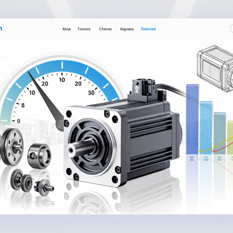
Define the Motion and Load Requirements
Before comparing motor ratings, describe the actual motion:
travel distance, move time, acceleration, dwell, and reversals. Then estimate the load’s inertia, friction, and external force. For a rotary axis, required torque includes the torque needed to accelerate the combined motor-and-load inertia. A heavy fixture that starts and stops every second can demand far more peak torque than its steady movement suggests.
Small detail, big difference.
Separate continuous torque from peak torque, and check both against the planned duty cycle. IEC 60034-1 classifies motor duty into ten types, S1 through S10, highlighting how operating patterns affect thermal requirements. The U.S. Department of Energy’s motor-load guidance reports that many induction motors reach peak efficiency near 75% load; this is not a servo sizing rule, but it cautions against oversized motor choices. Servo loads vary, so verify the candidate against its torque-speed curve and drive limits. A common mistake is sizing from payload weight alone. Include transmission ratio, friction, cable drag, and worst-case acceleration. If the load data is uncertain, measure a representative cycle; estimates can be wrong.
Compare Motor Ratings and Performance Specifications
When choosing a brushless DC servo motor, compare continuous torque and rated speed under the same operating conditions. A motor may show impressive peak torque, but that figure usually applies only briefly. Check the torque-speed curve, rated voltage, and current together. A motor that reaches the required speed without enough torque may stall under load. Heat matters, too: continuous current can warm the motor and shorten its service life if cooling is limited.
Tips: Match the motor’s continuous rating to your real workload, not just a short test. Allow a margin for acceleration and load changes. Check the stated duty cycle and cooling method.
Then compare encoder resolution, rotor inertia, and feedback compatibility with the drive. Higher resolution can support finer positioning, but it does not guarantee better system accuracy. Cable length, mechanical play, and tuning also affect results. If the load starts and stops often, compare acceleration limits and peak-current requirements. Datasheets can be awkward to compare; test conditions are not always identical. I have found that a simple side-by-side table helps expose missing details before selection.
How to Choose a Brushless DC Servo Motor? - Compare Motor Ratings and Performance Specifications
The motor ratings below are representative comparison points, not specifications for a particular product. Use the motor’s datasheet and drive specifications to confirm suitability for your application.
| Rating or Selection Factor |
100 W Class |
200 W Class |
400 W Class |
What to Check |
| Representative continuous power |
100 W |
200 W |
400 W |
Use continuous power for sustained operation; confirm the motor’s thermal and mounting conditions. |
| Example rated speed |
3,000 rpm |
3,000 rpm |
3,000 rpm |
Match the rated speed to the application’s operating point. Check the permitted speed range and any field-weakening limits. |
| Calculated rated torque at 3,000 rpm |
0.318 N·m |
0.637 N·m |
1.273 N·m |
Calculated using torque (N·m) = power (W) ÷ angular speed (rad/s). Actual datasheet torque may differ due to the specified rating point. |
| Peak torque |
Check motor datasheet |
Check motor datasheet |
Check motor datasheet |
Compare peak torque and its allowed duration with acceleration, load changes, and emergency-stop requirements. |
| Rated and peak current |
Check motor and drive datasheets |
Check motor and drive datasheets |
Check motor and drive datasheets |
Verify continuous and peak current compatibility. Current depends on the motor’s torque constant and the drive’s commutation method. |
| Feedback device |
Encoder or resolver, depending on the motor configuration |
Check feedback type, resolution, electrical interface, and compatibility with the servo drive and required positioning accuracy. |
| Torque-speed curve |
Review for the full duty cycle |
Review for the full duty cycle |
Review for the full duty cycle |
Confirm that required torque is available at the required speed, including acceleration and continuous operating points. |
| Thermal and duty-cycle limits |
Check datasheet and installation conditions |
Check datasheet and installation conditions |
Check datasheet and installation conditions |
Account for ambient temperature, cooling, mounting, load inertia, and how often the motor accelerates or stops. |
| Mechanical fit |
Check frame size, shaft, flange, and allowable loads |
Verify shaft dimensions, flange pattern, connector clearance, and radial and axial load limits. |
| Typical selection focus |
Compact, lower-power motion axes |
Moderate-power motion axes |
Higher-power motion axes |
Choose from the complete duty cycle and system requirements—not power rating alone. |
Choose Compatible Feedback, Drive, and Control Systems
Choosing a brushless DC servo motor means matching its feedback device, drive, and controller as one system. Start with the motion profile: note peak speed, continuous torque, acceleration, and required positioning accuracy. Then check whether the encoder type, resolution, supply voltage, and signal format are supported by the drive. Incremental feedback may suit repeatable moves after homing; absolute feedback can retain position information after power loss. Details matter. Also confirm the drive supports the motor’s commutation method and peak phase current, not just its rated power.
Compatibility affects more than commissioning time. The IEA’s 2011 report on electric motor-driven systems estimates that motors account for about 69% of industrial electricity use. That figure covers many motor applications, but it underscores why efficient, correctly matched operation matters.
Check the controller’s communication protocol, update rate, and available tuning tools before purchase. A fast network cannot fix poor encoder scaling. Nor can a capable drive compensate for an unsuitable control loop. During testing, watch for following error, overshoot, and heat at the motor housing. A tidy bench test is only provisional; cable routing and electrical noise can change results inside a real cabinet. I still double-check feedback polarity, because one missed setting can reverse the expected response.
Validate the Selection Through Sizing and Testing
How to Choose a Brushless DC Servo Motor?
Validate the Selection Through Sizing and Testing
A servo motor’s peak-torque rating can look convincing on paper, but the duty cycle tells a fuller story. The International Energy Agency’s 2011 report on electric motor-driven systems estimates they use 43–46% of global electricity. The U.S. Department of Energy’s 2014 motor systems sourcebook reports a 68% share of U.S. manufacturing electricity. These figures cover broad motor systems, not servo motors alone, but they underline why real operating conditions matter.
Build the sizing model from the actual motion profile: load inertia, acceleration time, speed, pauses, and starts per hour. Compare RMS torque with the motor’s continuous rating, then check peak torque duration against its limits. Include gearbox losses, friction, cable drag, and regenerative energy. My first sizing pass is rarely right; small friction loads are easy to overlook. Test under load.
Use a dynamometer or representative machine load to check torque, speed, current, and position error across the full cycle. Repeat tests after the motor reaches operating temperature, and verify performance at expected supply-voltage limits. Log results against the selected drive’s limits, not just the motor’s catalogue values. If the measured temperature or tracking error drifts, revise the assumptions and repeat the test. A neat spreadsheet cannot replace a warm motor and a real load.