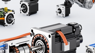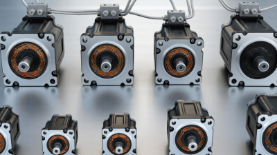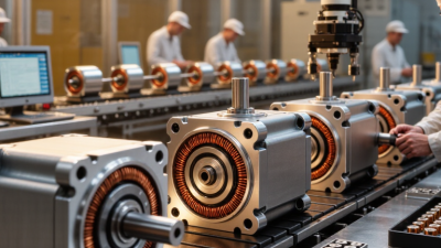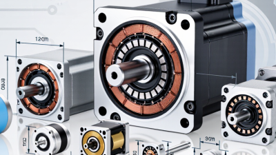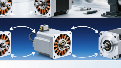
Choosing a Frameless Brushless Motor in 2026 requires more than comparing catalog torque ratings. The right choice must fit the complete mechanism: rotor, stator, bearings, encoder, housing, drive, and thermal path. A motor can look powerful on paper yet fail inside a compact robotic joint.
“Performance is a system property, not a motor specification,” says Dr. Kevin Craig, a motion-control educator and robotics engineer. This principle deserves attention. The motor, amplifier, feedback device, and mechanical load must work as one controlled system. Otherwise, impressive peak torque may become useless after several minutes of heat buildup.
Begin with the real duty cycle. Record continuous torque, peak torque, speed, acceleration, ambient temperature, and operating time. Then examine the motor’s torque constant, winding resistance, rotor inertia, back-EMF, and allowable temperature rise. Small details matter. A few extra grams can reduce responsiveness. Poor heat transfer can shorten service life.
For robotic joints, gimbals, medical instruments, and precision automation, frameless construction can save space and reduce mechanical interfaces. It also creates integration risks. The designer must align the rotor carefully and control bearing runout. Cable routing matters too.
Do not trust one graph.
Compare independent test data, supplier tolerances, encoder compatibility, production experience, and long-term support. Ask for samples before final approval. Test the motor under the actual load, not only on a laboratory bench.
This guide explains how to select a Frameless Brushless Motor with clearer engineering judgment. Some choices remain imperfect. That is normal. Reliable design comes from measuring those uncertainties before they become expensive failures.
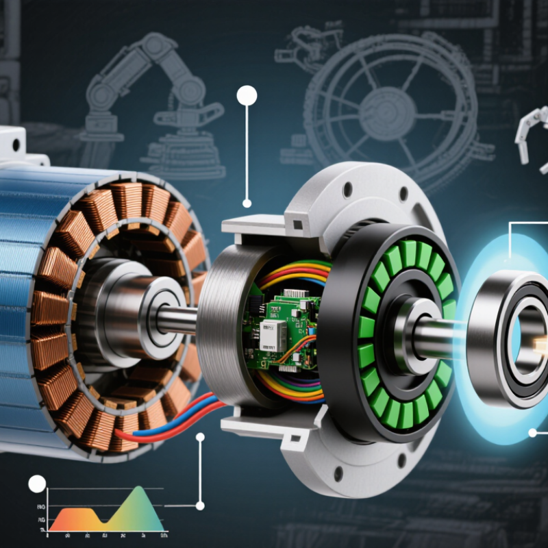
A frameless brushless motor is not a complete motor package. It is a separate stator and rotor, usually built directly into a machine’s structure. The stator carries copper windings, while permanent magnets sit on the rotor. An electronic controller switches current between the windings, creating a rotating magnetic field. The rotor follows that field and produces torque without brushes or mechanical commutation. Quiet operation matters here.
Feedback often comes from Hall sensors, an encoder, or a sensorless algorithm. An encoder gives accurate position data, especially during slow movement and rapid reversals. Sensorless control can reduce wiring, but starting performance may suffer under heavy loads. The U.S. Department of Energy’s Motor Systems Market Assessment reports that motor-driven equipment uses about 69% of industrial electricity. Small efficiency gains can therefore have practical value.
When choosing one in 2026, begin with continuous torque, peak torque, speed range, voltage, and duty cycle. Then check heat removal. A compact stator may reach its thermal limit faster than expected. The IEA 4E Electric Motor Systems Annex has repeatedly highlighted system-level efficiency, not motor efficiency alone. Shaft alignment, air-gap accuracy, bearings, and controller tuning all affect results. I have seen designs fail because engineers selected impressive peak torque but ignored continuous heat. That mistake remains common. Calculate the real load first.
| Selection Dimension | What a Frameless Brushless Motor Is or Does | Typical Engineering Data | How to Choose in 2026 |
|---|---|---|---|
| Motor Definition | A frameless motor is a separate rotor and stator set without an integrated housing, shaft, bearings, or finished mounting frame. | Core parts normally include a laminated stator, copper windings, permanent-magnet rotor, and rotor retention hardware supplied by the system designer. | Choose this format when the machine already provides its own shaft, bearings, structure, sealing, and mechanical alignment. |
| Operating Principle | The inverter energizes stator phases in a controlled sequence. The rotating magnetic field interacts with the rotor magnets and produces electromagnetic torque. | The electrical commutation method may be trapezoidal six-step control or sinusoidal field-oriented control. | Use field-oriented control for low torque ripple, quiet operation, smooth motion, and accurate servo positioning. |
| Required Torque | Torque is the rotational force available at the motor air gap and is the primary sizing value for acceleration, load movement, and disturbance rejection. | Continuous torque is commonly specified in N·m; peak torque is often available for a limited duration, such as 1–10 seconds, depending on thermal limits. | Select continuous torque above the calculated RMS load torque and peak torque above the maximum acceleration or disturbance requirement. |
| Speed Range | Speed depends on winding design, DC-bus voltage, back electromotive force, controller limits, and mechanical rotor constraints. | Many frameless servo applications operate from near zero speed to several thousand revolutions per minute; some high-speed designs exceed 10,000 r/min. | Verify the continuous speed, maximum mechanical speed, electrical frequency, and available voltage at the required operating point. |
| Torque Constant | The torque constant describes how much torque the motor produces per ampere of phase current. | It is normally expressed in N·m/A. In SI units, the torque constant and back-EMF constant are numerically related when compatible RMS or peak conventions are used. | Choose a higher torque constant when the drive-current limit is restrictive; confirm whether the specification uses peak, RMS, line-to-line, or phase values. |
| Winding Resistance | Resistance creates copper loss as current flows through the stator windings. | Copper loss follows Pcu = I²R and increases as winding temperature rises because copper resistance has a positive temperature coefficient. | Use hot resistance, not only room-temperature resistance, for accurate thermal and continuous-torque calculations. |
| Thermal Capability | Because the stator has no built-in housing, the machine designer must create the thermal path from the stator to the mounting structure. | Common insulation classes include Class F at 155°C and Class H at 180°C maximum rated insulation temperature; allowable winding temperature depends on the complete design. | Specify mounting material, contact area, thermal interface, cooling method, ambient temperature, and allowable winding temperature together. |
| Rotor and Stator Air Gap | The magnetic air gap is the clearance between the rotor magnets and stator teeth. It strongly influences torque, cogging, efficiency, and mechanical tolerance. | The specified air gap is usually a precision mechanical value and may range from fractions of a millimeter to several millimeters depending on diameter and construction. | Follow the manufacturer’s air-gap tolerance and runout limits; excessive eccentricity can cause noise, uneven torque, or rotor-to-stator contact. |
| Pole Count and Electrical Frequency | The permanent-magnet pole count determines how fast the electrical field cycles relative to mechanical speed. | Electrical frequency can be estimated by fe = p × n / 60, where p is pole-pair count and n is speed in r/min. | Confirm that the inverter supports the required electrical frequency, current-loop bandwidth, and commutation resolution. |
| Position Feedback | The motor itself may be supplied without feedback. The system integrator typically adds an encoder, resolver, Hall sensors, or another position device. | Incremental encoders may be specified in pulses per revolution; absolute encoders are commonly specified by resolution in bits, often 12–20 bits in servo applications. | Use an absolute encoder for immediate position knowledge and safety-critical motion; use Hall sensors when basic commutation and lower cost are sufficient. |
| Cogging and Torque Ripple | Cogging torque is position-dependent reluctance torque caused mainly by the interaction between rotor magnets and stator teeth. | Torque ripple is normally reported as a percentage of rated torque or as a peak-to-peak torque value; the result depends on winding, pole geometry, control, and load inertia. | For robotic joints, gimbals, scanners, and direct-drive stages, request measured cogging and torque-ripple data at the intended operating conditions. |
| Efficiency | Efficiency is the ratio of mechanical output power to electrical input power and varies with speed, torque, current, and temperature. | Motor losses include copper loss, iron loss, mechanical loss, stray load loss, and inverter loss; no single efficiency value represents the entire operating map. | Compare efficiency maps or operating-point data instead of relying only on a maximum efficiency figure. |
| Mechanical Integration | The customer supplies the shaft, bearings, rotor hub, stator mount, preload system, and structural alignment. | Critical parameters include rotor inertia, allowable radial and axial runout, mounting concentricity, shaft stiffness, bearing life, and fastening method. | Complete a tolerance-stack analysis before selecting the motor; the frameless format transfers integration responsibility to the machine designer. |
| Ingress Protection | A frameless motor does not automatically provide an IP rating because it has no complete factory housing or sealed cable interface. | IP ratings such as IP54 or IP65 apply to the completed enclosure and assembly, not automatically to an exposed rotor-stator kit. | Design the final enclosure, seals, coatings, drainage, and cable glands according to the required environmental protection level. |
| Drive Compatibility | The motor requires an electronic drive to regulate phase current, commutate the windings, and manage speed or position. | Important matching values include DC-bus voltage, continuous and peak phase current, back-EMF constant, inductance, resistance, pole pairs, and feedback interface. | Do not select the motor separately from the drive. Validate the complete motor-drive-feedback combination across the full speed-torque envelope. |
| Best-Fit Applications | The compact, integrated design is suitable for direct-drive mechanisms where low backlash, low acoustic noise, and high packaging flexibility are important. | Common application categories include robotic joints, gimbals, pan-tilt units, medical mechanisms, automation axes, reaction wheels, and precision rotary stages. | Choose a frameless motor when the benefits of custom mechanical integration outweigh the added design, assembly, alignment, cooling, and validation work. |
Note: Performance values for frameless brushless motors vary with diameter, winding, pole count, cooling, controller settings, mechanical integration, and duty cycle. Always verify the complete datasheet and test the integrated assembly at the required operating conditions.