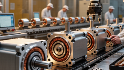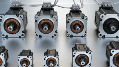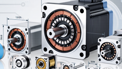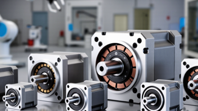
Choosing the right Frameless Dc Motor begins with the machine, not the catalog. A motor that looks ideal on paper may overheat inside a compact surgical tool, robotic joint, or camera gimbal. Real selection depends on torque, speed, voltage, thermal paths, available space, and duty cycle. I have learned that peak torque often receives too much attention. Continuous torque matters more when the mechanism moves for hours.
Small details decide performance. The rotor inertia, bearing arrangement, cable routing, and encoder position can change responsiveness and assembly effort. A frameless design also requires the customer to provide housing, bearings, preload control, and alignment. That freedom is powerful. It can also expose weak mechanical assumptions.
A reliable evaluation should compare measured data with the supplier’s test conditions. Check winding resistance, torque constants, speed limits, thermal impedance, insulation ratings, and allowable tolerances. Ask how continuous ratings were established, since ambient temperature and heat-sinking methods vary widely. Review drawings carefully; a two-millimeter interference can cancel an otherwise excellent design. Samples should be tested under the real load profile, including acceleration, stall events, vibration, and repeated starts. Independent testing is valuable. Yet no motor is universally best. A high-speed model may sacrifice low-speed smoothness, while a larger unit may simplify cooling but increase inertia. I would also question incomplete datasheets, even when the supplier appears reputable. Clear documentation, traceable quality control, and responsive engineering support are practical signs of authority. This guide examines those decisions with engineering evidence, application experience, and room for honest reconsideration.
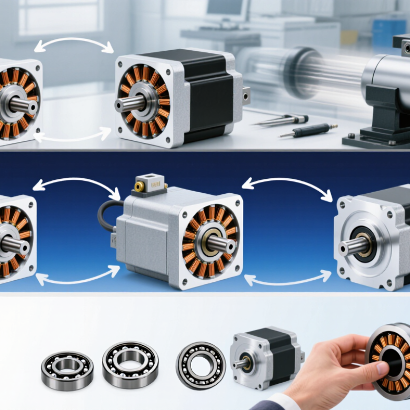
A frameless DC motor should begin with the machine, not the catalog. Define continuous torque, peak torque, speed, acceleration, and operating voltage. Then map the duty cycle: motion time, rest time, reversals, and overload duration. These details determine copper heating and the required thermal path. The U.S. Department of Energy’s Motor Systems Market Assessment reports that motor-driven equipment used about 70% of U.S. manufacturing electricity. Efficiency is not a minor specification.
Measure the load inertia and reflected inertia carefully. A large mismatch can cause overshoot, noise, or unstable control. Check the available bore, outer diameter, axial length, air gap, and mounting tolerances. A frameless kit needs the host mechanism to provide bearings, alignment, and heat dissipation. Confirm the rotor’s allowable speed and retention method. For feedback, select an encoder resolution that matches positioning accuracy, not marketing numbers. IFR’s World Robotics 2024 reported 541,302 industrial robot installations in 2023. That growth highlights demand for compact, repeatable motion, but every application still needs individual validation. My early estimates are often optimistic.
Tips: Build a torque-speed curve before choosing a motor. Test the worst-case ambient temperature. Include cable drag and seal friction. Ask for measured data at your voltage. Leave thermal margin. A prototype may reveal an overlooked resonance.
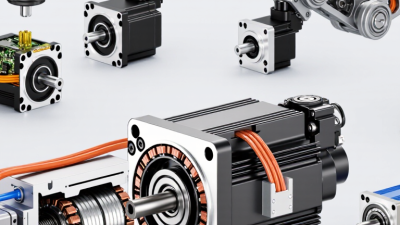
How to Choose the Right Frameless DC Motor?
When choosing a frameless DC motor, begin with the available space. Measure the stator diameter, rotor length, shaft clearance, and mounting depth. A smaller motor can simplify the mechanism, but it may produce less continuous torque. Check the housing temperature, too. Compact designs often lose heat more slowly.
Torque and speed must match the real load, not an ideal estimate. Review continuous torque, peak torque, and the required acceleration. A joint lifting a 2-kilogram arm needs extra torque during startup. It may need far less torque while holding position. Speed ratings can also mislead. A motor reaching 6,000 rpm without load may slow sharply under load. Examine the torque-speed curve at your intended voltage.
Power gives another useful comparison. Mechanical power is approximately torque multiplied by angular speed. Higher speed does not automatically mean better performance. Confirm winding resistance, current limits, efficiency, and duty cycle. In practical testing, run the motor for the longest expected operating period. Watch for rising temperature and unstable motion. I have seen a motor fit perfectly, yet fail because its continuous torque was overlooked. That mistake changed the design. Leave reasonable thermal and torque margins, but avoid oversized motors that add unnecessary mass and inertia. Recheck the calculation with measured load data. Estimates are helpful, but they are rarely complete.
Compare motor size, continuous torque, rated speed, and mechanical power to match the motor with the available space and load requirements.
The reference values represent typical frameless DC motor size classes without identifying any manufacturer. Mechanical power is calculated from continuous torque and rated speed using P = T × 2π × n / 60. Larger motors generally provide higher torque and power, while smaller motors can offer higher speed in compact assemblies.
A frameless motor is not a motor kit. It becomes part of your machine.
The rotor must match the shaft, bearing system, and expected overspeed. Check inertia carefully. A heavy rotor can reduce servo response. A thin rotor may save space but tolerate less mechanical abuse. I have seen promising prototypes fail because the shaft flexed under side loading.
The stator deserves equal attention.
Compare continuous torque, peak torque, winding temperature, and cooling conditions. Do not trust peak torque alone.
The U.S. Department of Energy estimates that motor-driven equipment consumes about 69% of industrial electricity, making efficiency and thermal design practical cost issues. IEA motor-system analyses also place motors near half of global electricity use. These figures explain why small efficiency losses matter at production scale. However, published values may reflect different duty cycles and measurement methods.
Mechanical integration often decides the real result.
Keep the air gap concentric, control axial preload, and provide a clear heat path from stator to housing. A compact aluminum mount may cool well, yet amplify vibration. Cable exits, resolver space, fastener access, and service replacement need physical checks. ISO 21940 balancing guidance can support rotor decisions, but it does not replace application testing.
My initial calculations once ignored assembly tolerance. The motor passed bench testing, then produced noise in the machine. Prototype with the actual housing, bearings, and controller. Test again.
How to Choose the Right Frameless DC Motor?
Check Feedback, Control, Thermal, and Environmental Needs
A frameless DC motor should be chosen around the machine, not its catalog torque. Start with feedback accuracy. Optical encoders support fine positioning, while Hall sensors suit simpler commutation and lower-cost systems. Check resolution, latency, alignment tolerance, and cable routing together. A high-resolution sensor cannot rescue a flexible shaft or noisy grounding. The U.S. Department of Energy’s 2016 Industrial Motor Systems Market Assessment reports that motor systems represent about 68% of industrial electricity use. That makes feedback quality an efficiency issue, not only a positioning issue.
Control compatibility comes next. Confirm bus voltage, current limits, commutation method, acceleration profile, and fault handling. Test the motor with the actual drive, load inertia, and motion cycle. Datasheet matching is not enough. Thermal review must include copper loss, iron loss, bearing friction, and heat flow through the mounting structure. Use continuous and peak torque separately. A short peak can be safe, but repeated peaks may create heat faster than the housing can remove it. IEC 60034-1 provides useful motor rating principles, yet real assemblies still need measured temperature data.
Environmental conditions often expose weak choices. Check dust, moisture, vibration, altitude, cleaning chemicals, and ambient temperature. IEC 60529 ingress ratings help define enclosure protection, but the complete assembly may have different weak points. The International Energy Agency estimates motor-driven systems consume about 46% of global electricity. In practice, run a thermal soak test at worst-case load. Also inspect sensor signals after vibration testing. No selection is perfect. I would rather reject an attractive torque figure than ignore condensation, connector strain, or an untested control loop.
Choosing a frameless DC motor starts with the machine, not a catalog. Define continuous torque, peak torque, speed, voltage, and available diameter. Check rotor inertia and the load’s reflected inertia. A motor that fits physically may still respond poorly. Measure the duty cycle. Will it accelerate every few seconds, or run continuously for hours? This detail changes the thermal decision.
Select a motor whose torque-speed curve covers the real operating point. Leave room for friction, voltage drop, and manufacturing tolerance. Confirm winding resistance and back-EMF from measured data. Do not rely on nominal values alone. Mount the stator and rotor with the intended bearings and air gap. Then test the complete assembly, not the motor on a loose bench. Record torque, speed, current, temperature, vibration, and acoustic noise. Use calibrated sensors and repeat each point after thermal stabilization. A cool first reading can mislead.
Run startup, reversal, overload, and endurance tests under realistic control settings. Watch winding temperature near the hottest accessible area. Compare results at low battery voltage and maximum expected load. This exposes weak margins early. I once trusted a clean spreadsheet too quickly. The prototype passed steady-speed testing but stalled during repeated reversals. The cause was control tuning, not motor size. That mistake changed our test plan. We now log transient current and settling time. Still, no test represents every installation. Review tolerances, cable length, cooling, and alignment before approval.
| Parameter | Candidate A | Candidate B | Candidate C | Selection or Test Requirement |
|---|---|---|---|---|
| Application and Mechanical Fit | ||||
| Typical application | Compact rotary actuator | Robotic joint or gimbal axis | High-speed precision spindle | Match the motor to the required motion profile and load type |
| Stator outer diameter | 70 mm | 90 mm | 70 mm | Must fit the available housing diameter |
| Rotor outer diameter | 42 mm | 55 mm | 42 mm | Must provide the required air gap and mechanical clearance |
| Motor axial length | 25 mm | 35 mm | 20 mm | Verify the available axial envelope and stack-up tolerance |
| Motor mass | 0.42 kg | 0.86 kg | 0.36 kg | Lower mass is preferred for moving axes when torque is sufficient |
| Rotor inertia | 0.000018 kg·m² | 0.000052 kg·m² | 0.000014 kg·m² | Consider rotor inertia when fast acceleration or reversal is required |
| Electrical and Torque Capability | ||||
| Nominal DC bus voltage | 24 V | 48 V | 24 V | Must be compatible with the motor drive and available power supply |
| Continuous torque | 0.65 N·m | 1.50 N·m | 0.42 N·m | Must exceed the calculated RMS load torque with a design margin |
| Peak torque, 1 second | 1.40 N·m | 3.20 N·m | 0.90 N·m | Must cover acceleration, disturbance, and short overload demands |
| Torque constant | 0.105 N·m/A | 0.180 N·m/A | 0.078 N·m/A | Use the verified torque constant for current and thermal calculations |
| Phase-to-phase resistance at 25°C | 1.20 Ω | 0.68 Ω | 0.92 Ω | Resistance rises with temperature and affects copper loss |
| Phase-to-phase inductance | 1.8 mH | 2.6 mH | 1.1 mH | Check current-loop bandwidth and drive switching compatibility |
| Maximum recommended speed | 4,000 rpm | 3,000 rpm | 8,000 rpm | Keep operating speed below the validated mechanical and electrical limit |
| Back-EMF constant | 9.8 V/krpm | 16.5 V/krpm | 7.2 V/krpm | Confirm that generated voltage remains within the drive voltage range |
| Thermal and Integration Factors | ||||
| Continuous current at rated torque | 6.2 A | 8.4 A | 5.4 A | Drive current rating should include continuous and peak requirements |
| Winding temperature rise at rated load | 54°C | 61°C | 49°C | Verify that winding temperature remains below the insulation-system limit |
| Thermal resistance, winding-to-housing | 1.8°C/W | 1.3°C/W | 2.1°C/W | Use the actual mounting structure because heat transfer depends on integration |
| Recommended housing material | Aluminum alloy | Aluminum alloy with heat spreader | Aluminum alloy | Provide a rigid, thermally conductive mounting surface |
| Position feedback compatibility | Incremental encoder or Hall sensors | Absolute encoder or resolver | High-resolution encoder | Select feedback according to positioning accuracy and commutation needs |
| Verification Test Results | ||||
| Test voltage | 24 V DC | 48 V DC | 24 V DC | Test at the intended operating voltage and controller settings |
| Measured continuous torque | 0.67 N·m | 1.47 N·m | 0.43 N·m | Measured using a calibrated dynamometer after thermal stabilization |
| Measured peak torque | 1.43 N·m | 3.08 N·m | 0.92 N·m | Measured during a controlled 1-second overload test |
| Measured no-load speed | 3,860 rpm | 2,920 rpm | 7,760 rpm | Should remain within the specified speed range |
| Measured efficiency at rated load | 82% | 86% | 79% | Measure electrical input and mechanical output under the same conditions |
| Measured winding temperature rise | 56°C | 64°C | 51°C | Compare with the permitted winding temperature and application duty cycle |
| Vibration velocity at rated speed | 1.6 mm/s RMS | 1.9 mm/s RMS | 1.4 mm/s RMS | Investigate imbalance, rotor alignment, bearing preload, and mounting stiffness |
| Positioning repeatability with selected feedback | ±0.035° | ±0.018° | ±0.022° | Test under the expected load, acceleration, and control-loop settings |
| Thermal endurance test | 2 hours at rated torque | 2 hours at rated torque | 2 hours at rated torque | Temperature must stabilize without exceeding the allowable limit |
| Selection Decision | ||||
| Load requirement used for comparison | 0.55 N·m continuous torque, 1.10 N·m peak torque, 3,500 rpm maximum speed | Includes approximately 20% continuous-torque margin and peak-load allowance | ||
| Mechanical fit | Pass | Review | Pass | Confirm rotor, stator, mounting, and cable clearances in the final assembly |
| Torque and speed capability | Pass | Pass | Insufficient continuous torque | Continuous and peak torque must satisfy the complete motion profile |
| Thermal performance | Pass | Review cooling capacity | Pass | Use the integrated housing and actual duty cycle for final validation |
| Overall recommendation | Recommended for compact actuator | Suitable when higher torque is required | Not recommended for this load requirement | Make the final decision only after prototype testing and thermal verification |